

Inspired by the thread in 2 Channel Debate, I decided to tastefully restore a pair of Stereo 20s we’ve had sitting around for a while. I thought it might be interesting to some if I documented my progress.
I started on one yesterday. It still needs a bit of cleaning. It’s in a very original condition.

Needs a new fuse holder. Luckily we have a spare Bulgin that is the same.

Completely untouched underneath! Sadly, a lot of the resistors had drifted off value significantly, as carbon composition resistors tend to do after a long time.
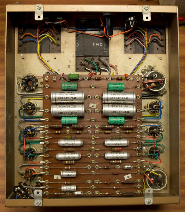

Fresh parts. All measure 0% with my multimeter set to ‘foo’. I have seen so many butchered Stereo 20s with ridiculously (physically) huge coupling caps, bypassed electrolytics, bypassed electrolytics with a bypassed bypass capacitor, and more. All manner of silly modifications that are likely to make things worse.

Progress yesterday after an afternoon’s work. I have made some progress today since then. As pictured the EL84 cathode resistors are not installed, and there are a few original components left. The 100R resistor is a 3W wirewound type (it looks a bit like a metal oxide but is WW). This is supposed to desolder itself and fall out in the event of an HT overload. As original, the leads of this resistor sit through the eyelets of the tags, which you’d think would defeat the purpose. The way I have it installed now is as such that it will fall right off in the event of an overload, but there may have been a reason for the original mounting. I will keep this in mind, it’s not like it’s difficult to change it back to original.
I may also (tastefully) fit an HT fuse. I don’t like modification for the sake of it, but I feel it would be worthwhile. This will be reversible. All components have been (and will be) replaced by equivalents. I have not yet gotten around to replacing the main smoothing capacitors, but I have some ready.

Here is a bit of progress from yesterday and today. Some new passives installed. I can’t seem to get a 91K version of these particular resistors. One of the phase splitter anodes needs this value, but luckily 100K in parallel with 1M happens to make nearly dead on 91K.

I have been preparing the capacitors. They were originally black, nothing a can of ‘Nissan Gold’ can’t fix! It’s not a perfect colour match but it’ll be less visually jarring than black ones.

Here’s the measured frequency response into 8 ohms from the amp. The measurement setup currently isn’t level calibrated. I have a measurements jig I made myself with built in attenuators and signal clamping diodes to protect the sound card. Works well enough for FR and distortion plots.
As you can see the channel matching is excellent, to within around 0.1dB, and this was with absolutely no effort to match any valves. Nice smooth HF rolloff too.

What amazed me was lack of high order harmonic distortion with this amp – this plot was taken at just shy of the start of clipping. The 5th and up harmonics are buried in noise. The spikes you see above 50Khz are my fluorescent lights. Things are even cleaner at lower levels. 50Hz sidebands can be seen which is to be expected due to the PSU ripple. This may be an argument for upping the capacitance.

The amp is now basically complete. I still need to get hold of a Bulgin mains plug, so in the meantime I have temporarily soldered in a mains cable. Here’s how the amp now looks

The sprayed capacitors turned out a lot better than I expected!

Underside shot of the amplifier. All passives have now been renewed. Note the placement of the fuse holder where the HT resistor was, and the relocation of said resistor. The resistor is still in the same place in the circuit. Thanks to the way the Leak comes wired, I was able to re-purpose the original wiring, non-destructively, to place a 250mA HT fuse after the CRC smoothing. You end up with a redundant red wire, which I just capped off with heat shrink and tucked away.

Close up of the relocated HT resistor

And the base-mount fuse holder, which sits neatly on top the original tags for the resistor, soldered in place.

Another shot of underneath

Thank you for reading and please comment.
About author of article:
Will is coming from South West in the UK and currently specialising in hifi servicing and sale.
Please check out his webpage at RADFORD REVIVAL – A resource for Radford & Woodside Hi-Fi

hello, i am about to do the same to my st20. looking at my amp ,the 0.1 caps, three have red stoppers on one side but on the opposite side on the other. at first i thought that the odd one had been put on by mistake but ive seen 4 or 5 pics on the net and they are all the same. are these cap ends polarity indicators. thanks for any reply.
Hi the best would be to contact an author of the article. You find it at the very end of page.- RADFORD REVIVAL
Hi there.
I have a 20 that I am working on. It is in far worse condition than the one here. I always fit a new pair of phono sockets for the input and have done the same as you with a fuse in the HT lead permanently on the rear panel.Since the one I have is going back to its owner when finished I have tried to bring it up to date without compromising its tone. I have therefore fitted decent speaker terminals. I have also removed the two pin mains distribution block on the rear and have replaced it with an internal mains filter fed from a new IEC mains socket input so that the tweak brigade can try different mains cables. I have had to do all of the resistors the power supply caps, the couplers to the EL84’s and the cathode decouplers on the input valves. Have you seen one with a bottom plate? So far the three or four I have done have been open but I understand there may have been a panel at some point either as an optional extra or was it a customer home built tweak?
I also have ideas to deal with the pre-amp which is also in my workshop. Have you done any of these?
Regards
Dave Tutt
The Varislope 2 is bad. (Starving mode, dead sounding alltogether) Give it a separate powersupply of 250 Volt and give the EF86 the standard 100 kOhm anode, 390 kOhm screen and 1 kOhm cathode resistor’s.
The powewrtransformer has only to deliver 8 mA so the enclosure of it is small and you’ll find it cheap in the dumpshop’s.
I can add that the underplate was an optional extra
Hi Dave
I too was looking for the base plate but have recently been told that no such part existed, there is a base plate for the preamp however. I now believe that the four metal catches with screws on the base are feet.
I woukd like to add a rebuttle regarding the negative claims aimed a The varislope, you only need to refer to some videos on YouTube to see this is not so, I have the Leak Point One Stereo preamp though and am very happy with the sonics. I would Nader how many out there make the spurious claims without actual experience. There are many negative internet comments about the ST20 too just as there are about Linn Sondeks and Porche 911s. Haha